Overview
Inspired by the classic ball-in-maze puzzle, I implemented a digital version as an embedded system on an STM32, the open-ended final project for McGill’s Microprocessors course (ECSE 444). Tilting the board moves a ball through a maze rendered on the OLED, with the motion driven by the microcontroller’s on-board inertial sensor.
What I did
- Read the on-board IMU over I2C and mapped board tilt to ball acceleration.
- Applied a Kalman filter to the noisy inertial measurements so the ball’s motion is smooth and stable rather than jittery.
- Rendered the maze and ball on the OLED display and handled the ball-vs-wall collision logic.
- Used the STM32’s ADC/DAC and peripherals for input and audio/output feedback.
- Wrote up the full build as a public tutorial (linked) and released the source on GitHub.
Approach and key decisions
Kalman filtering is the heart of it. Raw accelerometer data is noisy enough that a directly-driven ball feels twitchy and unplayable. Estimating the true tilt with a Kalman filter is what turns the raw IMU stream into smooth, controllable motion, the single decision that makes the puzzle actually feel good to play.
From prototype to PCB
The ECSE 444 build proved the concept on an STM32 dev board. The project then grew into a purpose-built custom PCB: a round, USB-C powered board designed in KiCad around an ESP32-S2 (later developed for UC Berkeley’s HOPE decal, with Jonathan Lin and Alejandro Munico). The board folds everything the breadboard prototype needed onto a single self-contained device:
- ESP32-S2-SOLO microcontroller in place of the dev board.
- USB-C input with USB protection, LiPo battery charging (MCP73831), and power management (AP2112K LDO plus a load switch) so it runs untethered.
- LSM6DSR IMU over I2C for tilt sensing, the same sensing role the on-board IMU played in the prototype.
- SPI OLED for the round maze display, plus reset/bootstrap and two user buttons.
- DRV2605 haptic driver and an ERM motor to add tactile feedback when the ball hits a wall.
Figures
Prototype (STM32)
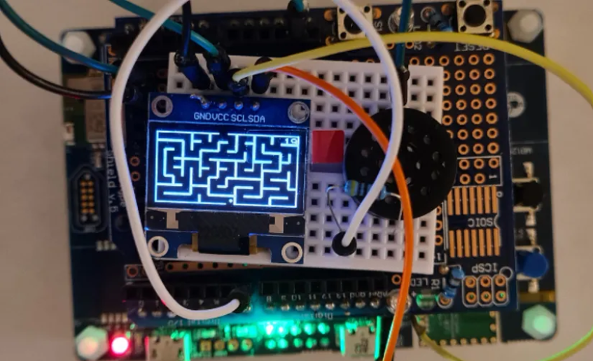 The original puzzle running on the STM32 dev board, maze rendered on the OLED.
Custom PCB
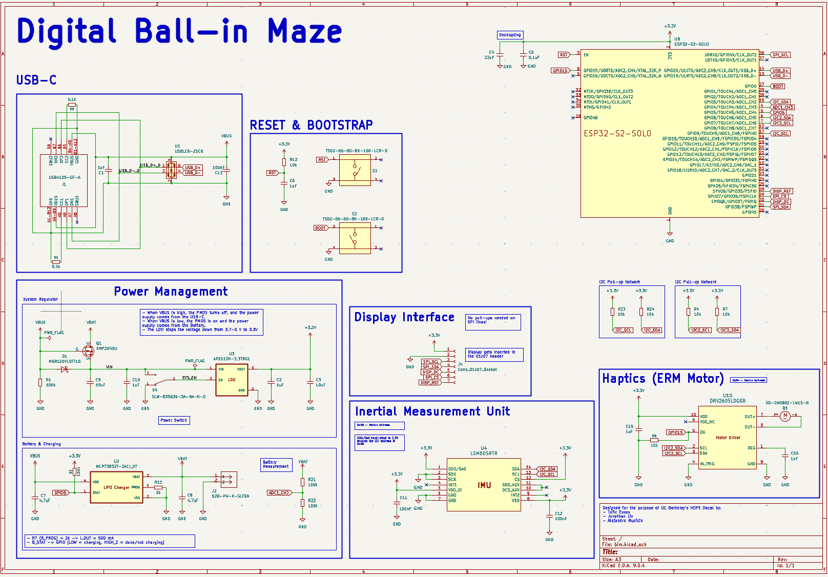 Custom board schematic: USB-C and battery power, ESP32-S2, IMU, SPI display, and haptics.
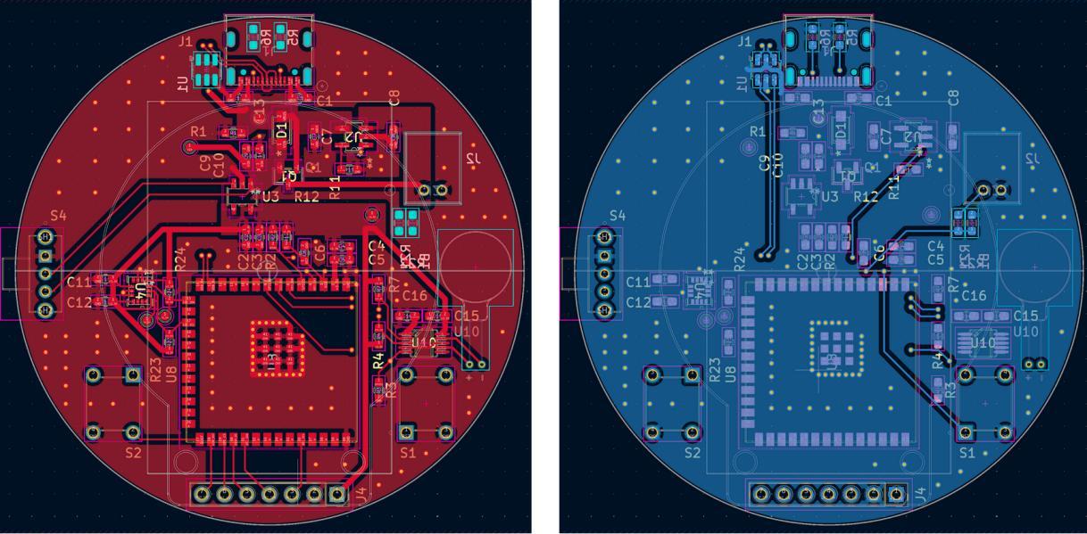 Round PCB layout, top (red) and bottom (blue) copper.
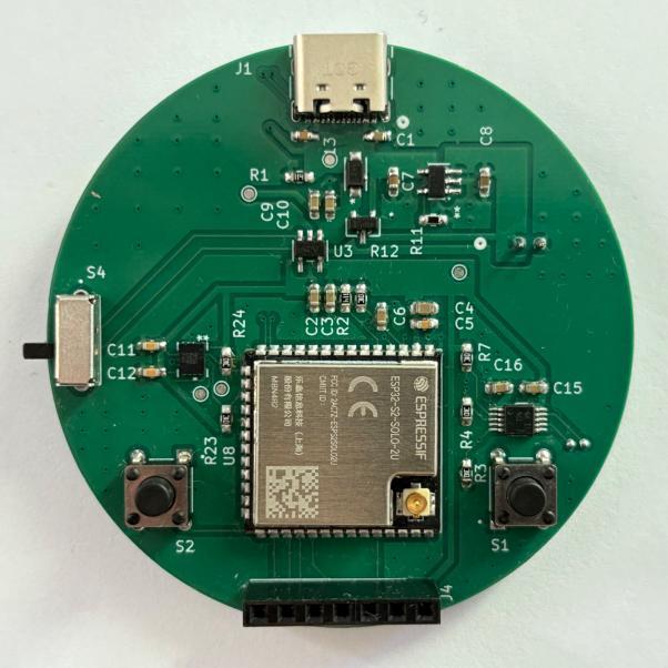 The fabricated and assembled board.
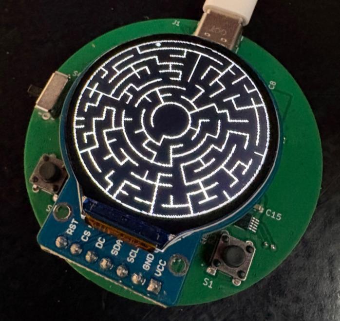 From prototype to product: the custom board running the maze on its OLED.