Overview
A set of six applications built on the Arduino Sensor Kit for McGill’s Embedded Systems (ECSE 421) labs, each implemented from an explicit state diagram:
- Pinball game
- Hot tub controller
- Elevator controller
- Skiing-safety system
- Plant watering system
- Earthquake elevator-safety mechanism
What I did
- Built each application in C++ on the Arduino Sensor Kit, reading sensors and driving actuators/displays.
- Modeled every application as a state machine before implementing it: defining states, transition guards, and the variables/inputs/outputs up front, then translating the diagram directly into firmware.
- Recorded video demos of each working application (linked below).
Approach and key decisions
State diagrams as the design language. The recurring theme across all six is that the behavior was specified as a finite-state machine first. For the hot-tub controller, that meant states like Idle, SetTemp, Heating, Hot, Cooling, and ShutDown with guarded transitions (e.g. temp < tempSelect / temp := temp + 0.2); for the elevator, it meant decomposing the system into communicating components, button panel, door system, controller, elevator car, accessibility chime. Designing at this level made the firmware a near-mechanical transcription of the diagram and the behavior easy to reason about and test.
Figures
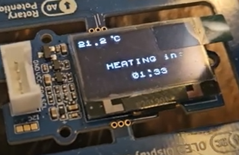
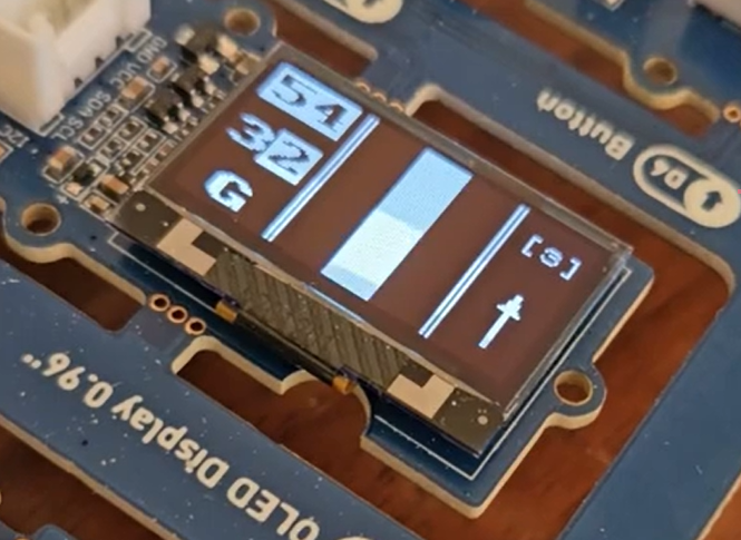 Hot tub controller (Fig. 27).
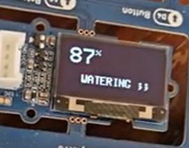
 Plant watering system (Fig. 28).
 Elevator controller (Fig. 29).
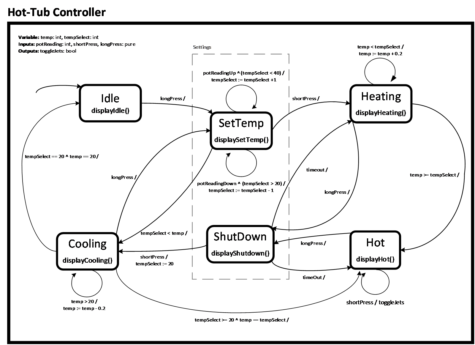 Hot-tub controller state diagram, the design was drawn before any code was written (Fig. 30).
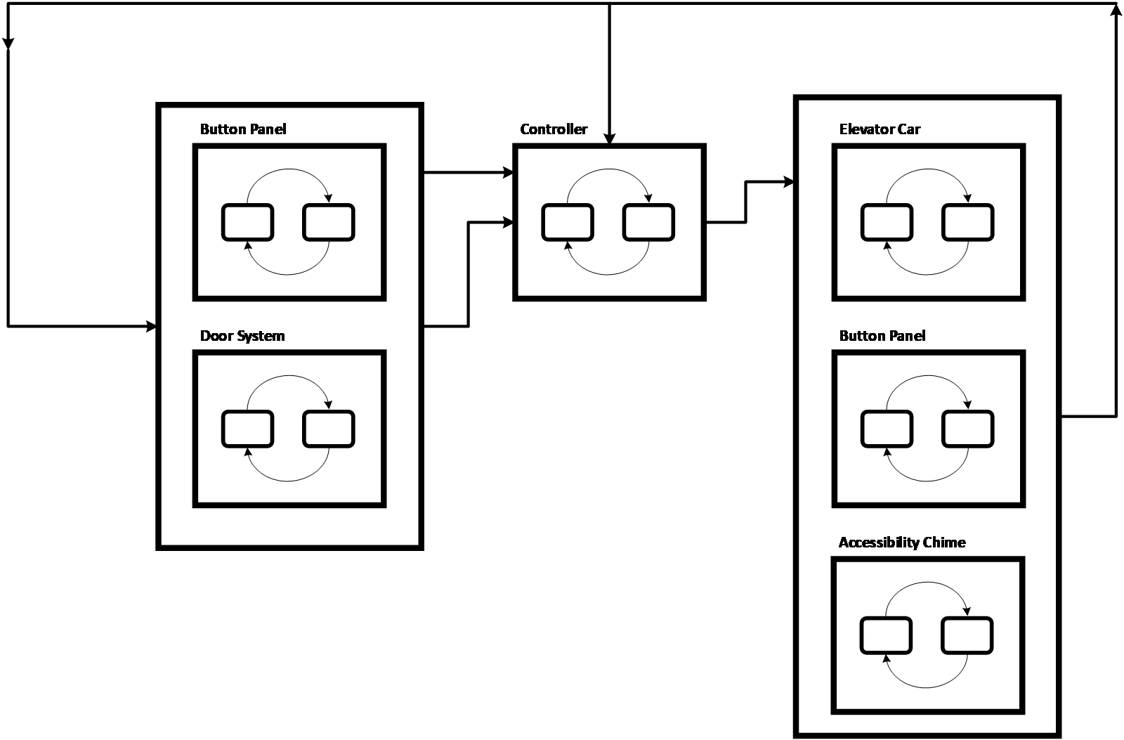 Elevator controller modeled as communicating components (Fig. 31).